
Ultimate 3D Printing Design Guide: CAD & Slicing Parameters for Perfect Prints
- shiva ganesh
- Aug 12
- 4 min read

This comprehensive 3D printing guide will teach you exactly what to consider when designing CAD models for FDM 3D printing. From overhangs to infill patterns, we’ll cover both geometric design rules and slicer settings to help you avoid failed prints and get professional-quality results every time.
Table of Contents
1. Introduction

Designing for 3D printing is more than just creating a shape in CAD and hitting “print.” Your print’s success depends on two main factors:
Geometric limitations of your 3D printer
Slicing parameters that turn your model into toolpaths
This guide combines real-world 3D printing examples with exact design and slicer settings to ensure your parts print successfully, whether they’re functional prototypes or display models.
2. Overhangs and Support Usage
Definition:
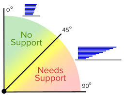
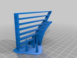
An overhang is any part of your model that extends outward without direct support from the layer below. In FDM printing, material is deposited layer-by-layer. If an overhang angle is too steep, the filament may droop.
Example:
A shelf-like projection extending 20 mm horizontally from a vertical wall.
Design Considerations:

Keep overhang angles ≤ 45° relative to vertical.
For steeper angles, add chamfers or gradual slopes.
Split the part into sections to avoid extreme overhangs.
Slicing Recommendations:
Enable supports for overhangs > 45°.
Use “Tree Supports” for minimal contact and easier removal.
Adjust support overhang threshold to ~50° if cooling is effective.
Best Practice:
Tilt roof-like features to reduce overhang angles, or add removable support
geometry.
3. Wall/Shell Thickness and Strength
Definition:
Wall thickness is the solid outer shell of your print. It impacts strength, surface finish, and water tightness.
Example:
A hollow rectangular tube for a lightweight frame.
Design Considerations:
Thicker walls = stronger parts but longer print times.
Use wall thickness as a multiple of nozzle diameter.
Avoid walls < 0.8 mm for a 0.4 mm nozzle.
Slicing Recommendations:
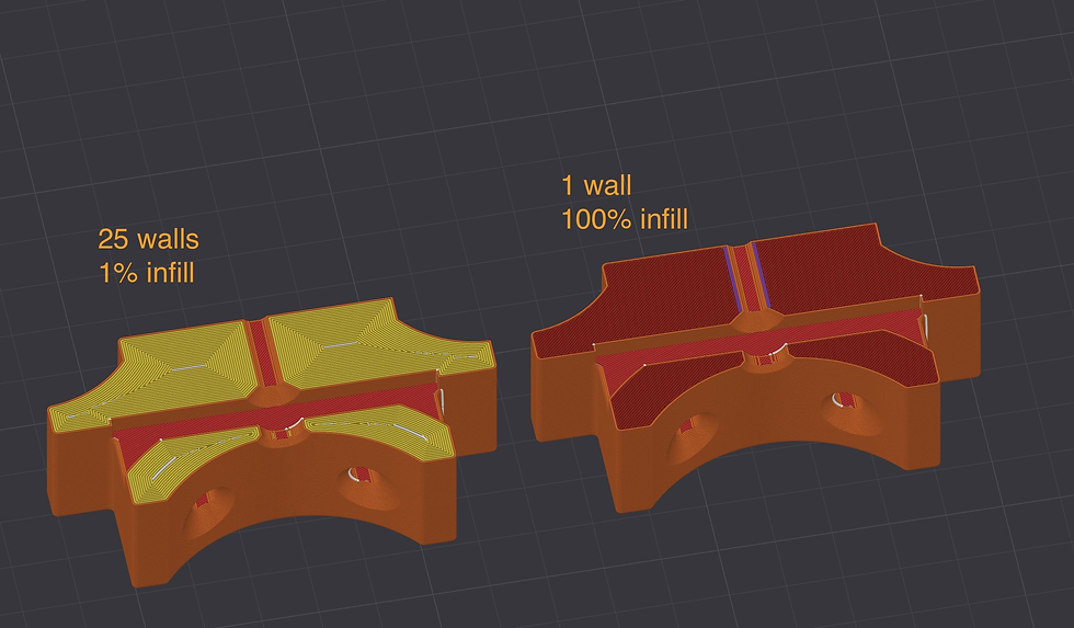
Structural parts: 3–4 wall loops (1.2–1.6 mm for 0.4 mm nozzle).
Increase walls for high mechanical loads.
Use adaptive layer height to balance finish and time.
Best Practice:
For structural frames, set at least 3 wall loops and match infill to load direction.
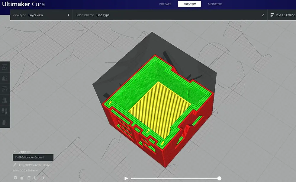
4. Infill Density and Pattern Selection
Definition:
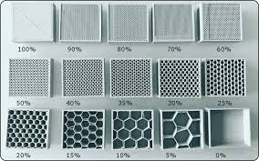
Infill is the internal structure between the outer walls, adding strength while reducing weight.
Example:
A large rectangular panel cover.
Design Considerations:
Higher infill = more strength, more weight.
Pattern affects stiffness: cubic = isotropic, gyroid = multi-directional strength.
Slicing Recommendations:
15–25% infill for decorative parts.
40–60% for mechanical loads.
Use cubic or gyroid for strength; lines for faster prints.
Best Practice:
For flat panels resisting bending, orient infill perpendicular to bending forces or use gyroid.
5. Bridging
Definition:
Printing across a gap without support.
Example:
A rectangular slot in a box wall.
Design Considerations:
Keep bridges ≤ 10 mm.
Add arches or ribs to reduce unsupported spans.
Slicing Recommendations:
Enable bridge speed control.
Increase cooling during bridging.
Best Practice:
For wide slots, break them into smaller bridged sections.

6. Hole Size and Clearance for Fits
Definition:
Clearance is the designed gap for fit and movement.
Example:
M8 bolt hole.
Design Considerations:
Holes print undersized in FDM.
Adjust CAD for press-fit vs slip-fit.
Slicing Recommendations:
Test printer tolerances.
Use horizontal hole expansion settings.
Best Practice:
For M8 bolts, design 8.3–8.5 mm diameter.
7. Thin Features and Minimum Wall Thickness
Definition:
Narrow projections prone to breakage.
Example:
Vertical clip tab.
Design Considerations:
Minimum 0.8 mm thickness for 0.4 mm nozzle.
Brace tall thin features.
Slicing Recommendations:
Add more perimeters.
Slow print speed.
Best Practice:
Add fillets at base for strength.
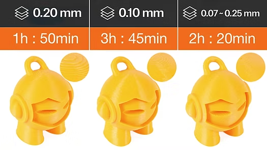
8. Layer Height and Resolution Choice
Definition:
Thickness of each layer.
Example:
Miniature figurine.
Design Considerations:
Lower heights = smoother finish, longer time.
Higher heights = faster, rougher finish.
Slicing Recommendations:
0.1–0.15 mm for detail.
0.2–0.28 mm for functional parts.
Best Practice:
Use 0.15 mm for gears — good balance of accuracy and time.
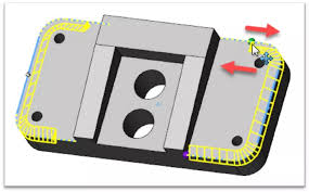
9. Part Orientation for Strength and Quality

Definition:
Positioning on the print bed.
Example:
Flat bracket.
Design Considerations:
Layer lines weakest in Z-axis.
Reduce supports with flat face to bed.
Slicing Recommendations:
Use auto-orient, then tweak.
Face critical surfaces upward.
Best Practice:
Lay bracket flat so layer lines run perpendicular to load.
10. Fillet and Chamfer Considerations
Definition:
Fillets = rounded edges, Chamfers = beveled edges.
Example:
Base of a column.
Design Considerations:
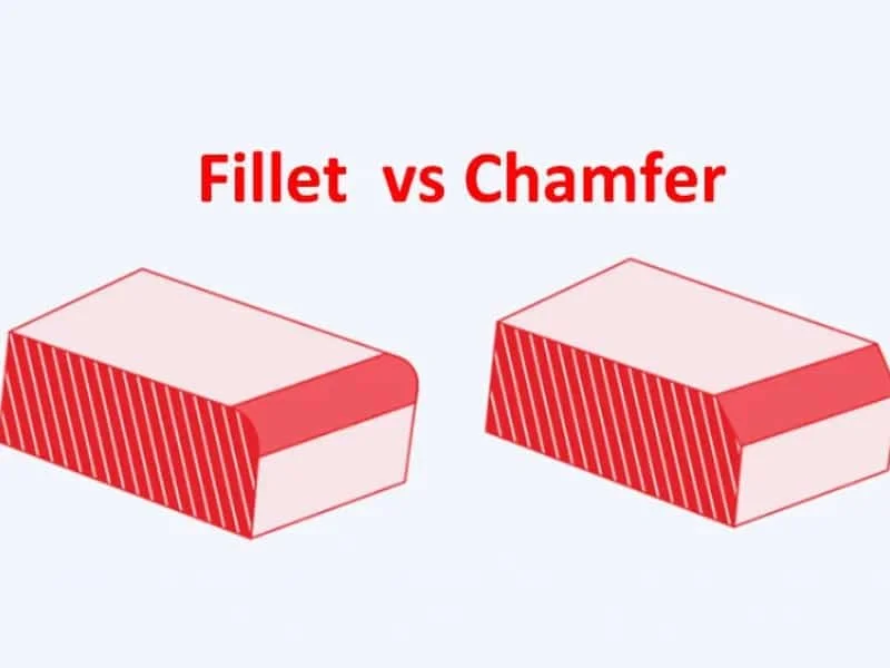
Fillets reduce stress points.
Chamfers improve printability.
Slicing Recommendations:
Add chamfers at base to avoid elephant’s foot.
Best Practice:
Use 2 mm fillet at base for strength.
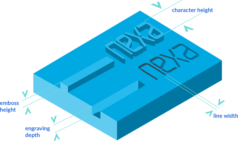
11. Text, Engravings, and Embossing
Definition:
Raised or recessed lettering/designs.
Example:
Embossed company logo.
Design Considerations:

0.4–0.6 mm stroke width minimum.
Raised text prints cleaner.
Slicing Recommendations:
0.1–0.15 mm layer height for details.
Best Practice:
Embossed letters at least 1 mm tall for clarity.

12. Hollow vs. Solid Design Decisions
Definition:
Choosing weight vs strength.
Example:
Cosplay helmet.
Design Considerations:
Hollow = lighter, may need supports.
Solid = stronger, heavier.
Slicing Recommendations:
2–3 walls, low infill for hollow parts.
Add escape holes if resin printing.
Best Practice:
Hollow helmet with 2 mm walls and 15% infill.

13. Tolerances for Moving Parts
Definition:
Gap between moving/interlocking parts.
Example:
Snap-fit hinge.
Design Considerations:
Too tight = fused, too loose = wobble.
Slicing Recommendations:
Print tolerance tests.
Best Practice:
Use 0.3 mm clearance per side.
14. Consolidated Best Practices Table
Feature | Design Tip | Slicing Tip | Best Practice |
Overhangs | ≤45° angle | Supports above 50° | Chamfer or reorient |
Wall Thickness | ≥2 walls (0.8 mm) | 3–4 walls for strength | Match nozzle multiple |
Infill | Based on load | 15–60% density | Gyroid for strength |
Bridges | ≤10 mm span | Increase cooling | Add arches |
Holes | Oversize in CAD | Horizontal expansion | +0.3 mm diameter |
Thin Features | ≥0.8 mm | More perimeters | Add fillets |
Layer Height | Match detail needs | 0.1–0.28 mm | Lower for detail |
Orientation | Load in XY | Auto/orient | Critical faces up |


Comments